This is an old revision of the document!
Building Elektrosluch Mini City
Introduction
Important notice: This kit requires skill and experience with soldering. We are providing it “as is”. We are confident it will work, when properly constructed according to the published design. We will not be able to help you with bad soldering jobs or other errors based on an insufficient standard of assembler workmanship.
Please do not attempt to construct the project if you do not fully understand it, or if you do not feel completely confident that you can build the project without further assistance.
If you never soldered before, we highly recommend watching these videos before you start with the kit. Soldering Tutorial Part by EEVblog Part 1 & Part 2
Required tools
For assembly of the Elektrosluch Mini City DIY kit you will need:
- a soldering iron (at least 20 W or better)
- solder (ideally 60/40, 0.75mm)
- side cutters
- screwdriver
Building guide

1. Examine the printed circuit board. You can see that it is covered with markings, indicating the correct placement of the components. During this tutorial, you will be mostly placing components (from the top side!) in the correct places and soldering them from the underside of the circuit board. After each soldering stage, you can cut off the leads of the components with side cutters, so they're not in the way.

2. It is best to start soldering the shortest components first and then move on to the larger ones. After you place the component legs through the holes, it may be handy to bend them in such a way that it wont fall out when the board is flipped over for soldering.
Our tutorial starts with resistors. Solder them all in their unique locations, according to the marks on the circuit board.

3. Continue with the yellow ceramic capacitors marked as 100 (10 pF). These will help to protect the circuit from very high frequencies beyond the audible range and oscillations. These are not polarity sensitive.

4. The next in line is the jack connector.

5. Push the potentiometer onto the board until it snaps into place and solder it in.

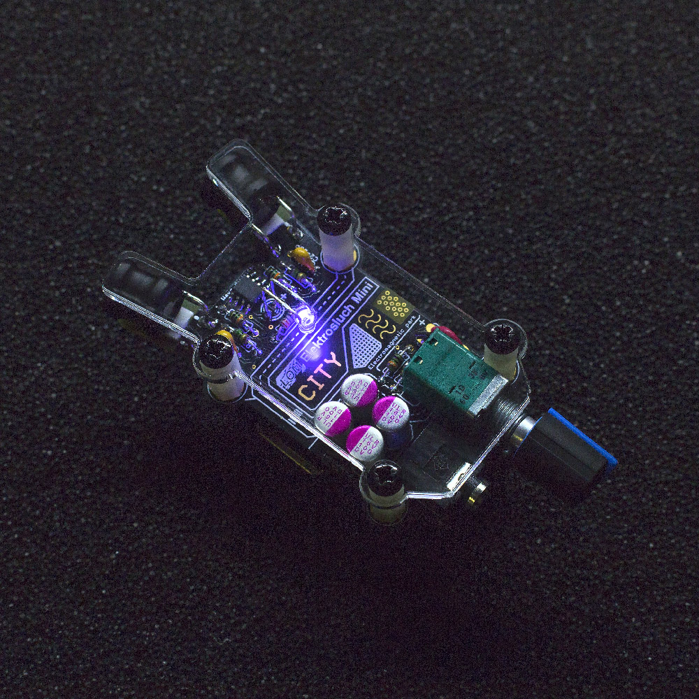
6. Solder in the four polymer capacitors. Beware of their polarity, minus (-) is marked on the body and plus (+) is marked on the circuit board! Double check you are soldering them in correctly, it isn't easy to desolder them. You can use the photo as a reference.

7. Remove the protective film from the sticky pads on the “antennae” of the circuit board and place the inductors as pictured. Solder them in.

8. Prepare your LED. If you want it to appear as on the photos (as a city light above the street), shape it as pictured. Be careful about the polarity – longer lead is ⊕ (positive).

9. Solder in the LED.

10. (Optional) Pre-tin the leads of the battery connector with solder.

11. Pull the wires through the hole next to the potentiometer as pictured and solder them in. This will act as a strain relief for the connection. The red lead goes to the plus and black to the minus.
13. Solder the battery connector in place as pictured. You can use the provided holes to pull the wires through
14. (Optional) Cover the battery with attached LOM sticker.
15. Check one more time if all the polarities (chip, capacitors, battery connector, battery) are correct. Reversing the polarity might irreversibly damage the circuit. Attach the battery and turn on the device with the potentiometer (it has a built-in switch!).
16. Check whether the LED lights up. Plug-in your headphones, turn the potentiometer almost all the way up and listen if you can hear the buzzing and humming of the electricity around you from both channels.

12. Now it is time to attach the battery holder to the bottom. Make sure that leads are cut as short as possible, so they won't make accidental contacts with the holder. Use the tape to attach the holder as pictured.

13. (Optional) Cover the battery with attached LOM sticker. 14. Check one more time if all the polarities (capacitors, battery connector, battery) are correct. Reversing the polarity might irreversibly damage the circuit. Attach the battery and turn on the device with the potentiometer (it has a built-in switch!).

This is how it should look from the side.

15. Put the knob on the potentiometer. It requires a bit of pressure, make sure you're holding the pot and pressing it against it, not against the whole device.

16. Attach the front cover using the 8 screws and 4 stand-offs.